As set out in previous chapters, Sustainable Drainage Systems (SuDS) must be integral to the master planning process. In a county where a third of the land is at or below sea level, and one that has been artificially drained for centuries, flooding is one of the biggest challenges we face. It is vital that new developments manage water carefully and sustainably, and do not cause flooding elsewhere.
Water has long been an integral part of the Lincolnshire landscape - so we want water to become a much more visible and tangible feature of new settlements too, one which can be enjoyed by everyone and retain the historic character of the county.
Lincolnshire County Council have long championed SuDS, and we expect very high standards of SuDS design - not just for flood risk reduction, but also the broader benefits that SuDS bring.
Traditional piped drainage offers few of the benefits of SuDS and should therefore be avoided wherever possible. Sustainable drainage features should be treated as the first choice for collecting, conveying and storing surface water runoff.
All SuDS proposed for adoption must also comply with LCC's Technical Specification, and final details will be approved at the detailed design stage
For Medium and Major developments (10 homes or greater) Lincolnshire County Council will be responding as the Lead Local Flood Authority (LLFA) and will review the design against the content of this code. Smaller developments need to follow the national SuDS standards but should also be in line with the requirements of this chapter of the code.
Medium and Major developments (greater than 10 homes) must comply with the requirements of this code.
Smaller developments (under 10 homes) should follow the requirements of this code where possible.
The SuDS approach requires runoff to be managed as close to source as possible, and for drainage systems to mimic natural drainage patterns, both of which can be achieved by following the SuDS management train. The drainage system should be thought of as a series of components rather than a single 'end of pipe' solution. This will help maximise the multiple benefits of SuDS systems and make it easier to integrate SuDS into a development.
SuDS systems should be designed in accordance with the SuDS management train.
The runoff destination for the drainage system - where it is discharging to - needs to be as close to source as possible to maximise the benefits of the SuDS approach. There is a well-established hierarchy of runoff destinations, in line with updated national standards.
The selection of runoff destination should be in line with the following hierarchy.
Designs can use multiple runoff destinations as appropriate.
| Priority | Destination |
|---|---|
1 | Collected for later re-use (e.g. rainwater butts, or use of green roofs) |
2 | Infiltrated to ground (soakaways, infiltration trenches, rain gardens) |
3 | Discharged to an above ground surface water body |
4 | Discharged to a surface water sewer, or another piped surface water drainage system |
5 | Discharged to a combined sewer |
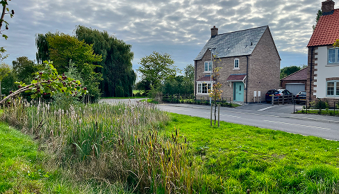
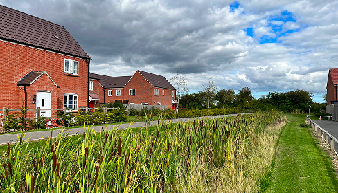
'Little and often' is the key to an effective well-designed SuDS system - allowing sustainable drainage features to be distributed throughout the site.
This means features to catch rainfall, such as permeable paving, swales and rain gardens, integrated into the streetscape, and large storage features such as ponds and basins that are integrated into public spaces. This is in contrast to 'end of pipe' solutions - piped drainage systems connected to large ponds and tanks.
During design, this can be achieved by splitting the site into sub catchments, each draining to a different SuDS feature.
Developments should distribute SuDS features throughout the site, using a mix of SuDS features to catch, convey, and store rainfall runoff.
Designers should use the sub-catchment approach to design and clearly mark the sub-catchments on submitted plans.
Any 'left-over' space in the public realm should be used for SuDS features where it is practical to do so (e.g. rain gardens or small ponds).
A sub catchment is the impermeable area that drains to a particular SuDS feature, with a flow control downstream. Flows are conveyed from one sub catchment to another in the SuDS management train (see above).
By splitting the site into smaller sub catchments, each with its own storage and flow control, it becomes easier to distribute storage throughout the site and simplifies the design process.
Think of it as a series of cascading features, all holding water back, rather than a network conveying water as quickly as possible.
Good SuDS are multifunctional. The latest national standards emphasise four pillars: quantity, quality, amenity, biodiversity.
SuDS features can be designed to accommodate other uses, such as:
Most storage in SuDS features, such as basins, will only be used in extreme events so it is possible to design features that will be dry most of the time.
SuDS should be designed to be multifunctional - integrating other uses such as amenity and traffic calming.
Where amenity uses, including play, are integrated with SuDS features such as basins or swales, they should be positioned above regularly flooded zones. Levels should be set to be appropriate to the sensitivity of the use, but as a general rule no amenity uses should be below the 1-in-5-year flood level.
Informal landscape areas can be designed to accommodate flood storage, supporting multifunctional SuDS where this can be achieved safely.
This design code is not a specification, and final approval will require compliance with the technical specification and standard details.
The adoption of SuDS features by LCC will depend on the context, as well as design and construction standards, and some features may need to be adopted and maintained by another responsible organisation, including Anglian Water, Severn Trent Water, or a private management company.
Where adopted, some features may still be subject to commuted sums depending on their design.
SuDS that are proposed for adoption must comply with the LCC technical specification and standard details.
Where SuDS conflict with highway safety or adoption requirements, including visibility splays, vehicle tracking, or road safety audit findings, those requirements take precedence and the SuDS design must be adapted accordingly during detailed design.
Any conflict with safety or adoption requirements must not be used as justification for reverting to a traditional below ground, positive drainage solution. There will normally be a suitable SuDS based solution.
Traditional positive drainage systems, such as piped networks that rapidly convey surface water, have long been the default approach to managing runoff from new development. However, even where attenuation tanks and flow controls are incorporated, such systems offer few of the wider benefits of sustainable drainage.
The cost difference between the traditional and SuDS approach is negligible, and internal LCC research has shown that traditional systems have a higher maintenance burden than SuDS - with a risk-based approach to maintenance and replacement, SuDS can be up to 27% cheaper than a positive drainage system.
There may be some instances where traditional systems are appropriate, as set out below:
Traditional positive drainage systems should only be used:
The lower lying areas of Lincolnshire, particularly the Wash, the Fens and The Grazing Marshes, have complex land drainage systems, managed by Internal Drainage Boards. Many of these areas sit below sea level and water levels are controlled through a network of pumping stations and sluices.
This means that many sites are likely to be intersected by land drains and ditches, not all of them visible. Careful design and construction will be needed to ensure that existing drainage systems are not disrupted, and consents may be required where works impact rivers, drains, watercourses and associated structures.
These drainage systems are typically shallow, which can make connecting new drainage systems challenging. Careful consideration of levels will be required, alongside the use of shallow SuDS systems such as swales to convey water.
Maintenance and management of watercourses is split between the following:
In total there are 14 IDBs operating across the Lincolnshire county area (see map below).
Managed watercourses, and associated structures, can be viewed on the LCC asset map.
Numerous authorities have statutory powers over watercourses in Lincolnshire. If you wish to undertake work on or near a watercourse, consent or byelaw relaxation may be required from the following:
Further details can be found on our website. Note that sometimes Internal Drainage Boards act as our agent for consenting and enforcement on ordinary watercourses. These areas are locally referred to as 'extended areas.'
Where work impacts a watercourse, developers must engage with the relevant authority (Environment Agency, Internal Drainage Board, or Lincolnshire County Council) before planning permission (full or reserved matters) is submitted.
Existing land drainage networks must be identified, assessed and diverted or incorporated into the new drainage system as necessary. Refer to Chapter A.5 (masterplanning) for further requirements.
This section relates to 'source control' features - those which are designed to collect, intercept and sometimes convey runoff. Source control features are at the start of the SuDS management train and as the name suggests, are located close to the source of the runoff.
The following features can be easily integrated into the street:
There are plenty of other solutions, such as green roofs and water butts, which are suitable for privately managed buildings and spaces, but sit outside the scope of this code.
Swales are one of the easiest features to integrate into streets - and are mandatory on certain Better Streets typologies. They are shallow, vegetation-lined channels that run alongside streets, collecting and conveying runoff while slowing the flow and filtering pollutants. They may be dry or hold a permanent water level. Most are grassed, but larger planting (including trees) can be incorporated.
Unlike swales, rills are hard landscaped linear features. This makes them appropriate where space is at a premium, for example in the Town and Heritage character areas. They can be dry or hold a permanent water level - in the latter case this can be combined with aquatic or marginal planting.
The following rules apply to swales. Refer to the technical specification for further guidance.
Swales must comply with the parameters set out in the table below
When swales are adjacent to the carriageway (i.e. not alongside parking) they must incorporate measures to prevent parking. Methods include:
Swales should be designed for infiltration or surface conveyance wherever possible.
Planting should be biodiverse, using the relevant seed mix in the technical specification.
Where rills have a permanent water level, they should be planted to enhance visual amenity and improve water quality.
Where swales have a longitudinal fall greater than 1 in 33 (3%), check dams should be provided at regular intervals to slow flow. Refer to the table below for spacing requirements.
Swales can include trees and shrubs as well as low-level planting.
| Minimum base width | 0.5 m |
|---|---|
| Maximum overall depth | 0.6 m |
| Minimum freeboard depth | 0.1 m |
| Maximum longitudinal fall | 1 in 16 (6.25%) |
| Maximum side slope | 1 in 3 (33.3%) |
| Check dam spacing | The base of the upstream should be level with the top of the downstream dam. |
Filter strips are grassed areas that run alongside streets, receiving sheet flow runoff from adjacent paved surfaces. They work by slowing the flow of water, allowing sediment and pollutants to settle out before runoff enters the next component - typically a filter drain or swale. They are simple to construct, easy to maintain, and can double as usable amenity space.
The following rules apply to filter strips. Refer to the technical specification for further guidance.
Grass filter strips must be set 35 mm below the adjacent road channel level to ensure runoff is received from the carriageway.
Filter strips must comply with the parameters set out in the table below.
Filter strips should receive runoff as sheet flow rather than concentrated flow. Kerb openings or dropped kerbs should be used where necessary to distribute flow evenly.
| Minimum width | 0.5 m |
|---|---|
| Maximum longitudinal fall | 1 in 20 (5%) |
| Maximum lateral slope | 1 in 5 (20%) |
| Grass height (maintained) | 75–150 mm |
Rain gardens are shallow, planted depressions that collect and treat surface water runoff. Water ponds temporarily on the surface before filtering down through soil, where pollutants are removed. They can be designed to infiltrate water into the ground or, where ground conditions are unsuitable, to drain via an underdrain connected to the wider drainage network, sometimes via a flow control.
They are multifunctional, bringing beauty and biodiversity to the street, and make excellent use of space. They can be constructed in buildouts to provide traffic calming, and can be integrated into public spaces, verges, junctions, or wherever there is 'left-over' space.
The following rules apply to rain gardens. Refer to the technical specification for further guidance.
Rain gardens must comply with the parameters set out in the table below.
When rain gardens are adjacent to the carriageway (i.e. not alongside parking) they must incorporate measures to prevent parking. Methods include:
Where runoff enters the rain garden as a concentrated (point) flow, the inlet must incorporate an energy dissipation structure, such as a stone apron, to prevent scour and distribute flow across the planting area.
Rain gardens must include an overflow - either to the below ground drainage system, or over ground towards the next feature in the SuDS train.
Rain gardens should be either infiltrating or under drained. Infiltrating designs are preferred where ground conditions allow.
Planting should be biodiverse and suited to the varying moisture conditions within the rain garden. A mix of at least 10 species should be provided - the mix should be based on the approved species list and agreed with LCC.
Flow should enter the rain garden via either:
Rain gardens can be constructed as a 'permeable tree pit' and incorporate trees and shrubs. Refer to the technical specification for specific requirements
| Minimum surface area | 10-20% of impermeable contributing catchment area (unless detailed calculations demonstrate otherwise) |
|---|---|
| Maximum ponding depth | 150–300 mm |
| Minimum freeboard depth | 100 mm |
The use of permeable surfaces throughout a development can be space efficient, avoiding the need for overly engineered drainage solutions and increasing land for housing or open space. Its capacity is such that adjacent impermeable areas can be allowed to drain onto it - for example an impermeable carriageway can shed into permeable parking bays.
Many different solutions are available, including:
Only permeable block paving will typically be considered for adoption by LCC. Other surfacing systems are suitable for privately maintained areas.
The build up can be designed to allow full or partial infiltration into the underlying sub soil and is typically under drained and connected to the drainage system.
The following rules apply to permeable paving. Refer to the technical specification for further guidance.
The choice of permeable paving must be in accordance with the Better Streets material palette.
In areas proposed for adoption, permeable paving systems must allow either partial or full infiltration into the subgrade - fully lined systems must not be used.
Permeable paving must only be used in the carriageway on lightly trafficked Type 2 streets and Type 3 streets.
Permeable paving must not be laid above utilities - an impermeable service strip can be created if required.
The groundwater table must be ≥ 1.0 m below invert level of the permeable paving construction.
Permeable paving should only be used when the soaked CBR of the subgrade is >2.5% - unless subgrade improvement can be carried out.
Where impermeable areas drain to permeable paving, the ratio of impermeable to permeable should be no greater than 2:1
Permeable paving can be used in parking bays and footways in Type 1 streets.
Where required by ground conditions, fully lined systems can be used privately maintained areas, subject to agreement with LCC and with technical justification.
It may be necessary sometimes to use gullies to collect surface water before discharging it into the sustainable drainage system - for example on Type 3.C or 3.D streets (refer to sub section B.02.01.05). The following rules apply to the use of gullies. Refer also to the technical specification.
Traditional gullies must only be used where a sustainable alternative is not feasible.
Gully spacing must be based on a maximum of one gully per 180m² of impervious area to be drained.
Double gullies must be provided at low points
Channel drains and slot drains must not be used.
Where used, gullies should be located:
Linear and combined kerb drainage systems can be used but only with prior approval from LCC.
Gullies can be used to provide an overflow point from rain gardens or swales.
This section relates to storage SuDS features - those that are designed to provide the bulk of attenuation and long-term storage volumes and are downstream of source control features such as swales and rain gardens.
The following features can be easily integrated into streets and public spaces on developments.
Ponds are among the most effective SuDS features for attenuation, pollutant removal, biodiversity and visual amenity. When well designed, they can become defining features of a place — focal points around which streets, squares and homes are arranged.
Multiple smaller ponds distributed across a site are preferable to a single large attenuation feature. Smaller ponds can be integrated into streets and squares — for example as a village pond or courtyard water feature — and can be soft or hard landscaped to suit their context.
When designed well, ponds can bring great amenity benefit and can even lead to higher property values.
The following rules apply to attenuation ponds. Reference should also be made to CIRIA C753 - The SuDS Manual for detailed design guidance.
Ponds must be integrated into the landscape and public realm as positive features of the development. They must not be located in leftover land at the edge of a site or hidden behind homes and buildings.
Ponds must be located downstream of other SuDS features as part of a management train. They must not be used as standalone 'end of pipe' attenuation.
Ponds must not be fenced off to prevent access. Designs should instead use a combination of gentle side slopes (except where site levels dictate retaining wall or steep slope), with marginal planting to define the water's edge.
Development should be arranged so that homes and streets front onto ponds, providing natural surveillance and integrating it as a central feature of the development.
Headwalls should be faced with brick, stone or other natural materials. Precast concrete and GRP headwalls should be avoided.
Ponds can be integrated into denser developments, such as in Town or Heritage character areas. This includes the use of hard-landscaped edges, stepped banks, or raised walls.
Basins are shallow depressions that are normally dry - filling temporarily during and after rainfall events to provide attenuation. As they only fill in extreme rainfall events they can be designed as multifunctional spaces, such as informal play areas, kickabout areas, or simply as attractive landscaped areas within the development. They are particularly well-suited to providing long term storage volumes, and attenuation storage for extreme storm events. They can be constructed as an online feature - with all flows routed through them, or as an offline overflow feature.
Where ground conditions permit, basins can drain via infiltration into the underlying soils, providing additional volume reduction.
As with ponds, well-designed basins can be beautiful additions to the landscape that provide character, amenity and biodiversity.
The following rules apply to basins; these largely mirror the rules for ponds. Reference should also be made to CIRIA C753 - The SuDS Manual for detailed design guidance.
Basins must be integrated into the landscape and public realm as positive features of the development. They must not be located in left-over land at the edge of a site, or hidden behind homes and buildings.
Basins must be located downstream of other SuDS features as part of a management train. They must not be used as standalone 'end of pipe' attenuation.
Basins must be designed to be shallow, with minimal water depth during most storm events. The maximum water level must be no greater than 1.0 m and only in extreme events (e.g. a 1-in-100-year return period).
Basins must be carefully landscaped and integrated with site levels and must not feel like 'engineered' features. Side slopes must be shallow (< 1 in 3) or stepped to allow safe access and egress.
Basins should include biodiverse planting, including trees and shrubs, not just amenity grass, in accordance with the approved species list.
Basins should be multifunctional wherever possible, providing amenity, play or recreational value when dry.
Areas of a basin that are multifunctional, such as play areas, should only be allowed to flood above the 1-in-5-year event.
Headwalls should be faced with brick, stone or other natural materials. Precast concrete and GRP headwalls should be avoided.
Basins can drain via infiltration, either fully or partially, where ground conditions are suitable.
In dense sites, such as in Town or Heritage character areas, basins can be hard landscaped and integrated into squares and other open spaces.
Underground storage is typically in the form of modular attenuation crates, oversized pipework or culverts. It is an option of last resort, as it is harder to maintain and does not provide the additional benefits of amenity and biodiversity, but can be useful in constrained sites.
Below ground drainage features will not normally be adopted by LCC. Culverts and pipes may be adopted by Anglian Water.
The following rules apply to underground storage. Refer to the technical specification for further guidance.
Underground storage must only be used when above ground storage options are not practical. For example, on infill sites in Town or Heritage character areas.
Modular attenuation crate systems must not be used below the adopted highway.
Oversized pipework and storage culverts may be used beneath adopted highway, subject to LCC technical specification requirements.
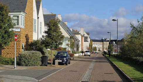
Planting street trees is one of the most effective design interventions we can make, a tree lined street will be:
Lincolnshire County Council and most districts have tree planting strategies in place with high ambitions for increasing canopy cover. Tree planting in new developments will be a vital part of this.
Lincolnshire County Council expect that all new developments will incorporate trees, and commuted sums will not be charged for new street trees where they comply with the requirements of this code. Please also refer to the requirements for existing trees in Chapter A.5 - Masterplanning
The key to successful tree planting is the principle of 'the right tree in the right place'. This section of the code sets out how to ensure that.
The following locations are suitable for tree planting within the adopted highway.
The following rules set out requirements for tree planting. Reference should also be made to the technical specification.
In streets, the benefits of trees need to be realised quickly, so 'standard' sized nursery trees are required to provide immediate impact. In open spaces, a mix is appropriate: some larger trees are needed to anchor the planting, but a higher proportion can be whips. Whips establish quickly, require less maintenance, and are more economical thereby enabling more trees to be planted overall
All Type 1 (Principal) and Type 2 (Residential) streets must include street trees within the adopted highway.
Tree pits and verges within 5.0 m of the pavement or carriageway must include root barriers or a root deflector.
New street trees must be over 1.5 m in height and a minimum 8 cm girth, equivalent to a 'standard' tree.
In open spaces, the planting mix must include a minimum ratio of one 'standard' tree to every ten 'whips'.
When mature, trees must have a clear height of 5.5 m between the carriageway surface and the lowest branch. A 2.6 m unrestricted clearance should be available over footway areas and 3.0 m over cycleways.
Type 3.A (shared space) and Type 3.B (edge lanes) should include street trees where possible.
Trees should not be planted within 2.0 m of a building. The exception is small fastigiate (column like) tree species with a low canopy spread.
Utilities and lighting should be coordinated around trees - no new light columns should be placed within 5 m of a small tree, or within 10 m of a large tree.
When trees are planted in verges, they should be spaced no more than 8.0 m apart. Elsewhere, spacing should be in accordance with the requirements of the street typology.
Trees in Town and Historic area types should be spaced regularly along the street to provide a formal character.
Trees in Rural area types should be planted at irregular intervals, and occasionally grouped, to provide an informal character.
Trees in the Suburban area type can be spaced regularly or irregularly.
The correct mix of species is vital to the long-term resilience of street trees. The selection of species is also important for the character of a street, and designers are encouraged to vary species across a development.
A full list of suitable small and large tree species is provided in the technical specification.
Tree species must be in accordance with the approved species list (Refer to Part C)
To ensure long-term resilience, no single tree species must account for more than 10% of the trees on a single street, and not more than 20% of a single genus and 30% of a single family.
Species selection must be guided by three considerations:
The mix of species should vary by street typology. E.g. the Principal Street should have different species to Residential Streets, which have different species to Tertiary Streets.
Open spaces, such as squares, greens, or basins, should include at least one large 'feature tree'.
Greenery works best when it is woven throughout a development, in verges, street trees, swales and small greens, rather than concentrated in a single area of 'public open space' at the edge of a site. As with SuDS, little and often is key. Planting should also reinforce local character and be designed for year-round interest without creating maintenance burdens.
Greenery must be distributed throughout the development.
Species must be in accordance with the species list contained in the technical specification.
Planting should provide a mix of species offering structure, colour and seasonal variation throughout the year.
Additional evergreen or perennial planting along the roadside can be provided. For example, as areas of bulbs and low maintenance shrubs. Proposals will be assessed on a site-by-site basis.
Verges and SuDS features offer significant opportunities for biodiversity. Wildflower planting is strongly encouraged wherever maintenance regimes allow, and mown amenity grass should be kept to a minimum.
Amenity grass must not be used as a default ground cover. Verges, banks and SuDS margins must include wildflower or low-maintenance native planting wherever possible.
Grass and wildflower seed mixes must be in accordance with the species list in the technical specification.
Mown grass should be limited to areas where it is functionally necessary – for example around play areas, in formal greens or drainage filter strips.
Native hedgerows are characteristic of Lincolnshire's landscape and provide significant biodiversity. Existing hedgerows need to be protected, and new hedgerows can be planted as an appropriate boundary treatment.
It is recognised that there are potential maintenance issues, such as where private boundary hedgerows encroach onto the public highway. LCC retains powers under the Highways Act 1980 to require the cutting back of vegetation in this scenario.
Where hedgerows form private boundaries adjacent to the highway, a minimum setback of 0.5 m should be incorporated between the hedgerow and the highway boundary to allow for growth and maintenance without encroachment.
Shrub species planted within the highway should be low maintenance. Native species are preferred.
Existing hedgerows can be integrated into the new adopted highway, for example by incorporating them into verges, or using them to define new pedestrian and cycle links.
Residents look after what they feel ownership of. Maintenance of highway greenery doesn't need to rest solely with LCC or a management company and there are opportunities on most developments to give residents genuine stewardship of planting and green spaces. Parish councils may also wish to use their powers under the Highways Act to take on a more active role. Developers who wish to maintain enhanced planting within the adopted highway can do so under agreement with LCC.
Residents, groups of residents, and businesses can be allowed to plant and maintain shrubs, plants and grass in designated areas. This will be subject to approval from LCC and may require a licence under Section 142 of the Highways Act 1980.
Parish councils can exercise their rights under Section 96(5) of the Highways Act 1980 to plant, and maintain greenery in the adopted highway, subject to LCC consent.